Dynamic Balancing Machine
Product Details:
Product Description
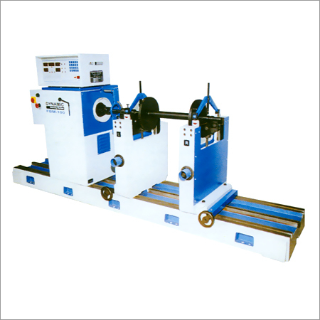
Dynamic Balancing Machine
BIE makes hard bearing type horizontal two plane dynamic balancing machine with microprocessor based/microcontroller based measuring panel. Machine model FBM-(M) is most suitable for balancing of different types of rotors like rotors of electrical machines, fly wheels, crankshafts, fly wheels, crankshafts cylinders, submersible pump rotors, etc.
Working on these machines is very simple. Double start push button is provided to start the machine. The cycle is fully automatic which starts the machine, measures and stores the unbalance in gms along with the angle for two selected planes on digital display simultaneously, and stops the machine (with brake, if machine is provided with electrical braking facility). The measuring cycle takes around fifteen seconds for smaller rotors. For higher capacity machine, the drive is provided through slipring motor to avoid any damage to drive coupling and other rotating parts in the drive system. Starting of these machines is done manually by cutting resistance in the starter in steps.
Keyboard facility is provided on measuring panel for data feeding of dimensions like A,B,C,RL and RR tolerance limits for both correction planes i.e. TLL, TLR can be fed so that when rotor is balanced within specified limits, respective LED glows up, indicating no further correction is required. For more details please refer features of microprocessor based/microcontroller based panel for dynamic balancing machines.
To increase the capacity of machine for extra long rotors, additional bed lengths can be provided, which can be aligned along with the basic machine beds. Facility for additional bed with gap bed arrangement is also possible to accommodate bigger diameter rotors. Higher capacity machines above 7000 kg. are provided with fixed separate drives and hence gap bed design is not possible for these machines.
Salient Features
Key Board
Key board is provided for data feeding. Data of rotor dimensions like A,B,C,RL and RR and balancing tolerance. TLL and TLR are fed by key operation hence, accuracy of data feeding is accurate upto 1 digit.
Digital Display
For Unbalance indication: Amount of unbalance along with angular position is displayed separately for both correction planes simultaneously. Hence angle and amount indications are ore accurate and precise as compared to conventional analogue meters.
Digital Display For Speed Indicator
For digit display is provided for indicating balancing speed in RPM as a standard feature.
Auto Stop
Machine once started, stops automatically after the unbalance readings are stabilized.
Simultaneous Indication
Amount and angle of unbalance in both planes is displayed simultaneously an remains stored till next run. This totally eliminates operation of plane selector switch and reduces additional time required for unbalance stabilization.
Auto Range
Depending upon unbalance amount, fine or coarse range gets automatically selected till rotor gets balanced with tolerance multiplier operation (manual) is totally eliminated.
Tolerance Indicators
Separate LED's for both correction planes are provided which glow when unbalance is reduced within selected balancing tolerance.
Data Store
Data for various rotors can be stored against respective rotor type nos. Hence no need of measuring rotor dimensions or rotor data feeding when balancing of same type of rotor is to be carried out. Just call rotor type no and machine is ready for balancing.
Self Check
Panel is provided with “Self Check” mode to check proper functioning of digital display. (In this mode, Led's will glow in cyclic operation) This helps immediate fault detection.
Technical Specifications
| Model | Unit | FBM- | FBM- | FBM- | FBM- | FBM- | FBM- | FBM- | FBM- | FBM- | FMB- |
| Weight of rotor | kg | 0.5-10 | 1 - 30 | 2-50 | 3-100 | 10-300 | 20-650 | 10-1000 | 30-3000 | 70-7000 | 100-10000 |
| Maximum diameter of rotor | mm | 500 | 500 | 500 | 1000 | 1000 | 1200 | 1600 | 2000 | 2400 | 2400 |
| Maximum distance between bearings | mm | 480 | 480 | 1100 | 1350 | 1350 | 1650 | 1650 | 2400 | 3300 | 3300 |
| Maximum distance between bearings | mm | *50 | *50 | *50 | **100 | **100 | **100 | 350 | 500 | 500 | 500 |
| Journal diameter range over std. roller carriage | mm | 5 - 50 | 5-50 | 5-50 | 20-100 | 20-100 | 20-100 | 25-140 | 35-200 | 55-300 | 55-300 |
| Balancing speed(n) | rpm | 1000 | 700 | 700 | 600 | 500 | 350 | 350,700 | 300,600 | 200,400 | 200,400 |
| Power of drive motor | H.P | 0.33 | 0.75 | 0.75 | 2 | 3 | 5 | 7.5 | 20 | 30 | 40 |
| Acceleration capability GD2N2 | kgm2n2 | 0.29x10⁶ | 0.37x10⁶ | 0.37x10⁶ | 0.88x10⁶ | 3-90x106 | 8.56x10⁶ | 14.12x10⁶ | 88x106 | 160x106 | 216x106 |
| Minimum unbalance mass measured | gm | 0.01 | 0.1 | 0.1 | 0.1 | 0.1 | 0.1 | 0.1 | 0.1 | 1 | 1 |
| Maximum unbalance mass measured | kg | 0.4 | 4 | 4 | 4 | 4 | 4 | 4 | 4 | 4 | 4 |
| Unbalance reduction ratio | % | 95% | 95% | 95% | 95% | 95% | 95% | 95% | 95% | 95% | 95% |
| Minimum achievable unbalance per rotor weight | Microns or gm/kg | 0.5 | 0.5 | 0.5 | 0.5 | 0.5 | 0.5 | 0.5 | 0.5 | 0.5 | 0.5 |
Other Products in 'Testing & Measuring Equipment' category

GST : 24AAECK9581F1ZC
|
|
|
 |
KRUTAM ENTERPRISES
All Rights Reserved.(Terms of Use) Developed and Managed by Infocom Network Private Limited. |


